Reverse Input Clutch Assemble
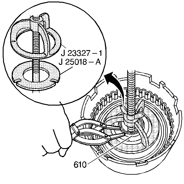
Special Tools
- J 23327-1: Forward Clutch Spring Compressor (Bridge)
- J 25018-A: Clutch Spring Compressor Adapter
- J 44571-1: Reverse Input Clutch Piston Installer
- Inspect the reverse input clutch piston (607) for the following:
- Damaged or porosity
- Ring groove damage
- Install the reverse input clutch inner and outer seals (608) on the piston.
- Install the J 44571-1: piston installer inner (2) and outer (1) reverse input clutch piston installer.
- Install the piston (607) into the housing (605).
- Remove the J 44571-1: piston installer.
- Inspect the reverse input clutch spring assembly (609) for bent, broken, distorted or damaged springs.
- Install the reverse input clutch spring assembly (609).
- Install the J 23327-1: compressor (bridge) and the J 25018-A: spring compressor adapter.
- Install the reverse input clutch spring retainer ring (610).
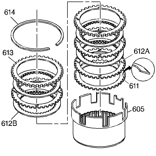
- Inspect the belleville plate (611), the fiber plate assemblies (612B), the steel turbulator plates (612A) and the selective backing plate (613) for the following items:
- Damaged tangs
- Delamination
- Excessive wear
- Heat damage or wear
- Surface finish
- Flatness
- Install the reverse input clutch belleville plate (611), with the inner diameter up, into the reverse input clutch housing and drum assembly (605).
- Install the reverse input clutch plates starting with a steel turbulator plate (612A) and alternate with a fiber plate assembly (612B).
- Install the reverse input clutch selective backing plate (613).
- Install the reverse input clutch retaining ring (614).