Control Valve Body Disassemble
- Remove the manual valve (340).
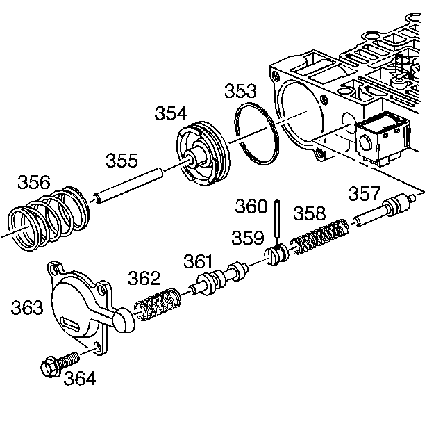
- Remove the forward accumulator cover bolts (364) and the forward accumulator cover (363).
- Remove the forward accumulator spring (356), forward accumulator piston (354), and the forward accumulator pin (355).
- Remove the low overrun valve spring (362) and the low overrun valve (361).
- Remove the coiled spring pin (360) and the bore plug (359).
- Remove the forward abuse valve spring (358) and the forward abuse valve (357).
- Remove the solenoid retainer (395) and the 1-2 shift solenoid (367A).
- Remove the 1-2 shift valve (366) and the 1-2 shift valve spring (365).
- Remove the solenoid retainer (395) and the 2-3 shift solenoid (367B).
- Remove the 2-3 shuttle valve (369) and the 2-3 shift valve (368).
- Remove the coiled spring pin (360).
- Remove the 1-2 accumulator valve sleeve (372).
- Remove the 1-2 accumulator valve (371) and the 1-2 accumulator valve spring (370).
- Remove the solenoid retainer bolt (364A) and the solenoid retainer (378). Remove the pressure control solenoid (377), note orientation upon removal.
- Compress the actuator feed limit valve spring (375).
- Remove the bore plug retainer (395) and release the spring slowly.
- Remove the bore plug (376).
- Remove the actuator feed limit valve spring (375) and the actuator feed limit valve (374).
- Remove the bore plug retainer (395) and the bore plug (381).
- Remove the 3-2 downshift valve spring (390) and the 3-2 downshift valve (389).
- Remove the coiled spring pin (360) and the bore plug (359).
- Remove the reverse abuse valve spring (388) and the reverse abuse valve (387).
- Remove the bore plug retainer (395) and the bore plug (381).
- Remove the 3-4 shift valve spring (386) and the 3-4 shift valve (385).
- Remove the bore plug retainer (395) and the bore plug (381).
- Remove the regulator apply valve (380) and the regulator apply spring (397) and the isolator valve (398).
- Remove the bore plug retainer (395) and the bore plug (381).
- Remove the 3-4 relay valve (384) and the 4-3 sequence valve (383) and the 4-3 sequence valve spring (382).

WARNING:
Refer to Valve Springs Can Be Tightly Compressed Warning
.