Removal Procedure
WARNING: This page is about a different variant/trim than selected.
- Remove the control lever and boot. Refer to Control Lever and/or Boot Replacement .
- Drain the transmission fluid if necessary. Refer to Transmission Fluid Replacement .
- Remove the transfer case assembly. Refer to Transfer Case Assembly Replacement .
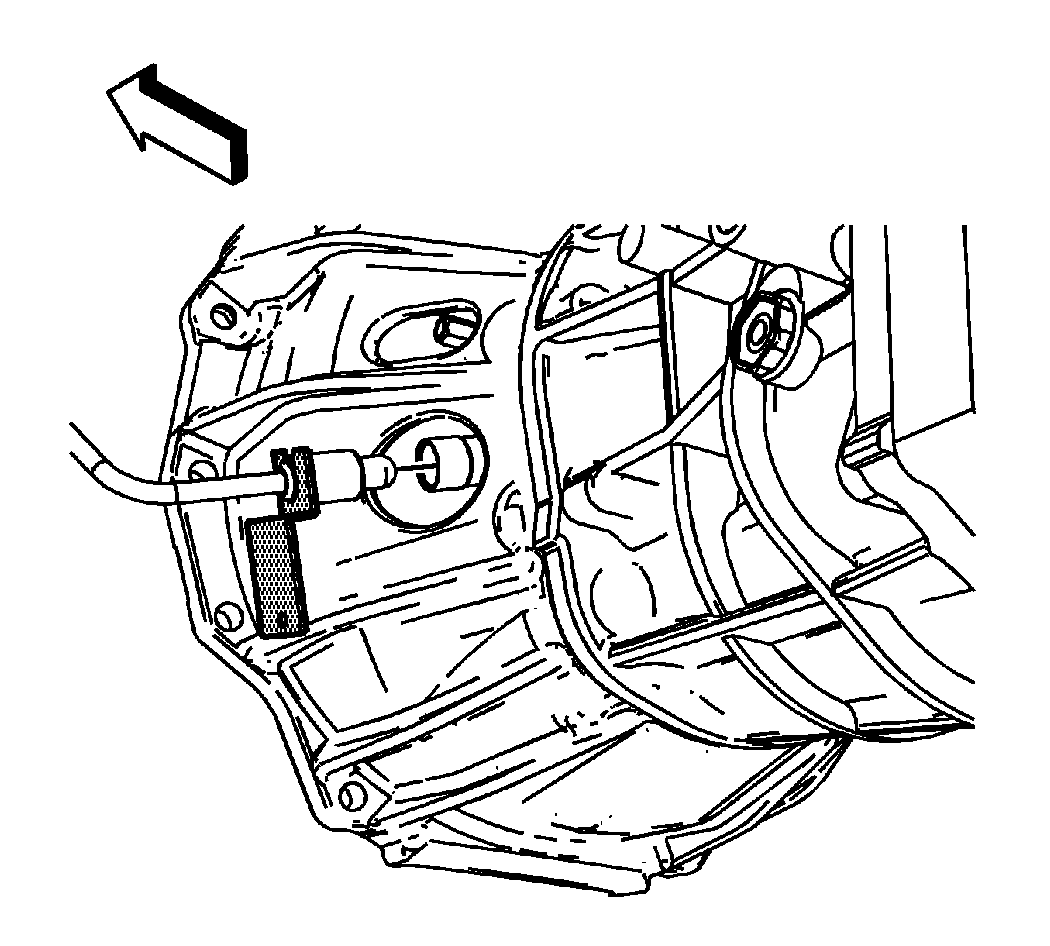
- Using the J 42371
push back on the white plastic sleeve on the quick connect in order to separate the hydraulic clutch line from the clutch actuator quick connect.
It is not necessary to plug the lower hose end or slave cylinder fitting as they are equipped with check valves, only minimal fluid loss may be experienced.
- Disconnect the engine wiring harness electrical connector (1) from the backup lamp switch (2).
- Disconnect the engine wiring harness clip (3) from the clip bracket, and position the harness over the transmission.
- Disconnect the engine wiring harness clip (1) from the clip brackets, and position the harness aside.
- Remove the nuts securing the fuel hose/pipe brackets to the transmission, and position aside.
- Support and secure the transmission using a suitable transmission jack.
- Remove the transmission crossmember. Refer to Transmission Support Crossmember Replacement .
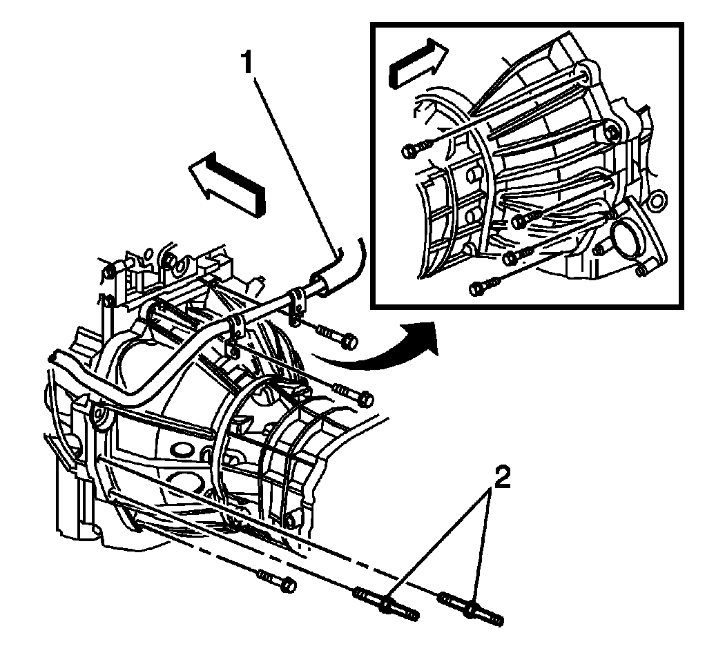
- Remove the service slot plug (1).
- Remove the 7 transmission mounting bolts and 2 studded mounting bolts (2).
- Remove the remaining transmission mounting bolts (2).
- Pull the transmission straight back off the clutch hub splines.
- The catalytic converter
- The clutch assembly
- The engine wiring harness
- The fuel hose/pipe brackets
- The heater pipe
- Using the transmission jack, carefully lower the transmission from the vehicle.
 Courtesy of GENERAL MOTORS CORP.
 Courtesy of GENERAL MOTORS CORP.


NOTE:
Do not allow the transmission to hang from the clutch assembly.
NOTE:
Ensure clearance is maintained between the transmission and the following: