Output Shaft Disassemble
WARNING: This page is about a different variant/trim than selected.
Special Tools
- J 8001-3: Dial Indicator
- J 22912-B: Split-Plate Bearing Puller
- J 26900-12: Dial Indicator - 1-10 mm
- J 26900-13: Magnetic Indicator Base
- J 45869: Gear Protector Plates
For equivalent regional tools, refer to Special Tools .
- If RWD, remove the speed sensor reluctor wheel rear retaining ring.
- Remove the speed sensor reluctor wheel.
- Remove the speed sensor reluctor wheel locating ball.
- Remove the speed sensor reluctor wheel front retaining ring.
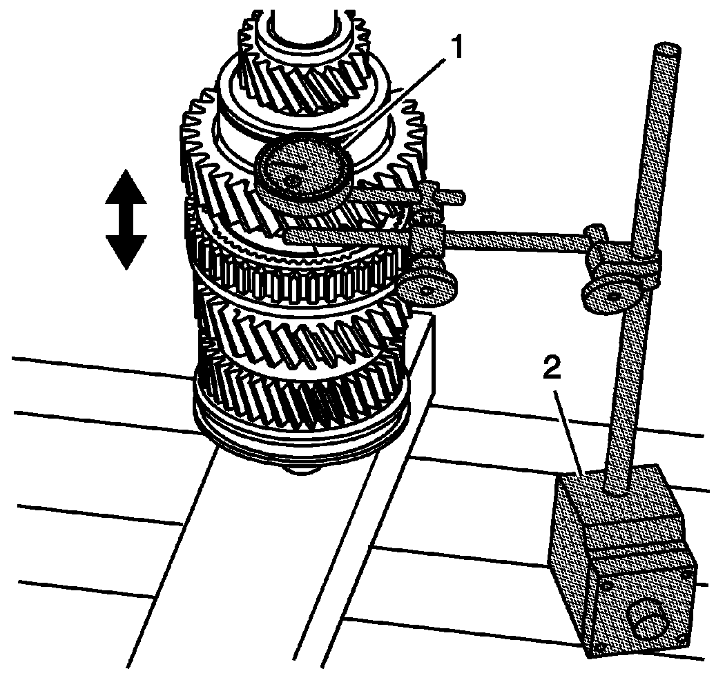
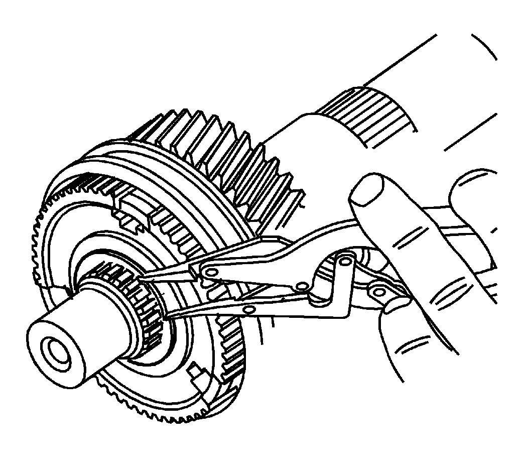
- Using J 8001-3:
indicator or J 26900-12:
indicator (1) and J 26900-13:
base (2), measure the 1st gear axial play.
- Standard Clearance: 0.20-0.45 mm (0.0079-0.0177 in)
- Maximum Clearance: 0.50 mm (0.0197 in)
- Position J 8001-3: indicator or J 26900-12: indicator (1) on the top of the gear teeth.
- Zero the gauge.
- Lift up on the gear to measure the clearance.
- If the clearance exceeds the maximum, refer to Gears and Shafts Cleaning and Inspection .
- Using 2 screwdrivers and a hammer, remove the 5th gear retaining ring.
- Using a hydraulic press, remove the 5th gear and the output shaft rear bearing.
- Remove the following components from the rear of the output shaft:
- The 5th gear (150)
- The output shaft rear bearing (193)
- The 1st gear thrust washer (116)
- The 1st gear (110)
- The 1st gear bearing (113)
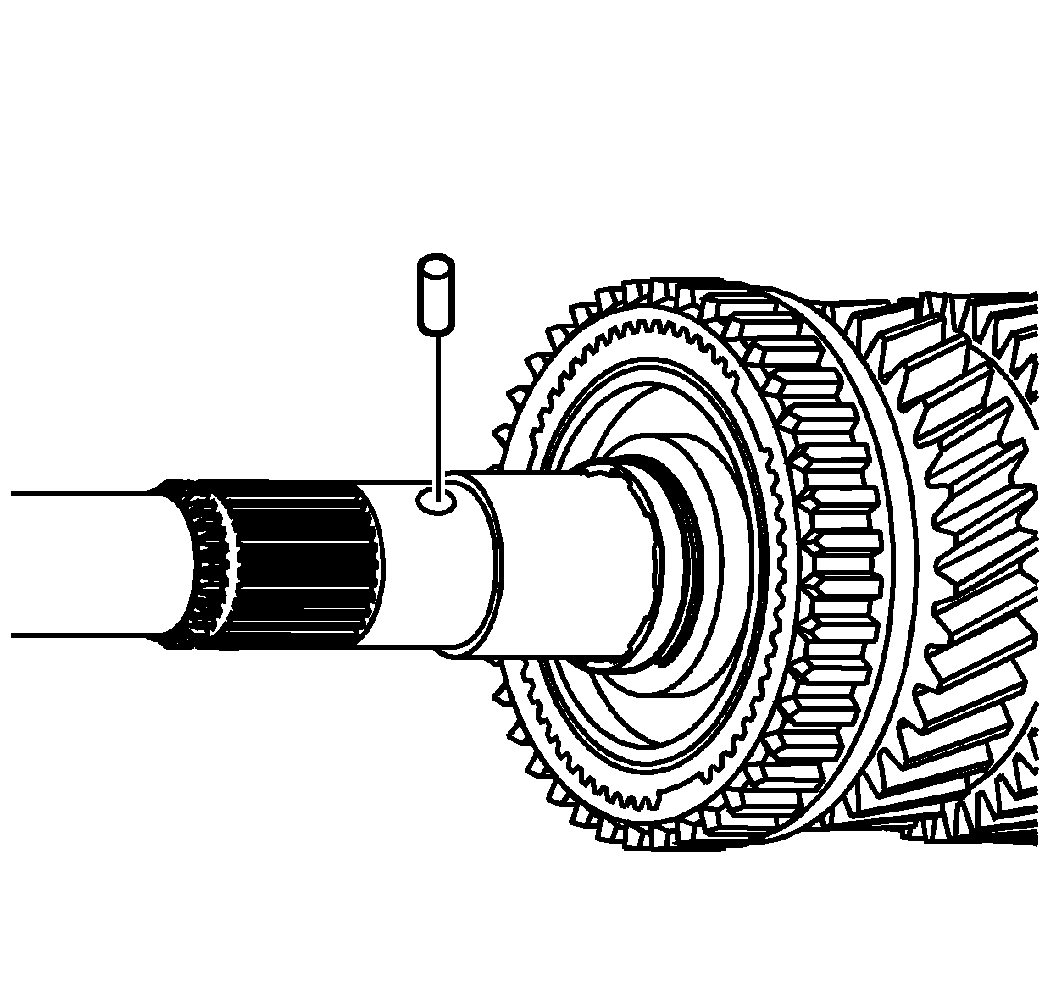
- Remove the 1st gear thrust washer lock pin.
- Remove the 1st gear bearing spacer.
- Using J 8001-3:
indicator or J 26900-12:
indicator (1) and J 26900-13:
base (2), measure the 2nd gear axial play.
- Standard Clearance: 0.10-0.25 mm (0.0039-0.0098 in)
- Maximum Clearance: 0.30 mm (0.0118 in)
- Position J 8001-3: indicator or J 26900-12: indicator (1) on the top of the gear teeth.
- Zero the gauge.
- Lift up on the gear to measure the clearance.
- If the clearance exceeds the maximum, refer to Gears and Shafts Cleaning and Inspection .
- Using 2 screwdrivers and a hammer, remove the 1st/2nd synchronizer hub retaining ring.
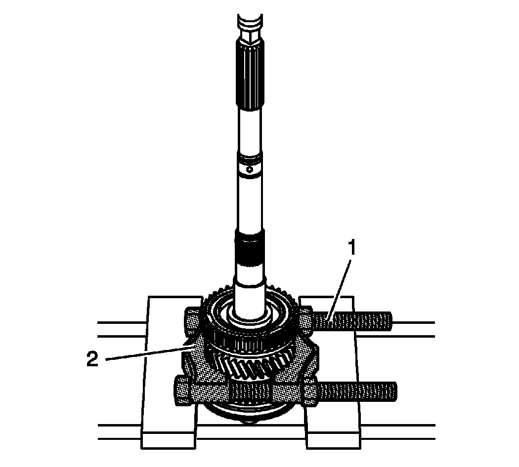
- Install the J 45869: plates (1) onto the J 22912-B: puller (2) to protect the gear teeth from chipping.
- Install the J 22912-B: plates (2) with the J 45869: plates (1) under 2nd gear.
- Using a hydraulic press, remove the 1st/2nd gear synchronizer hub.
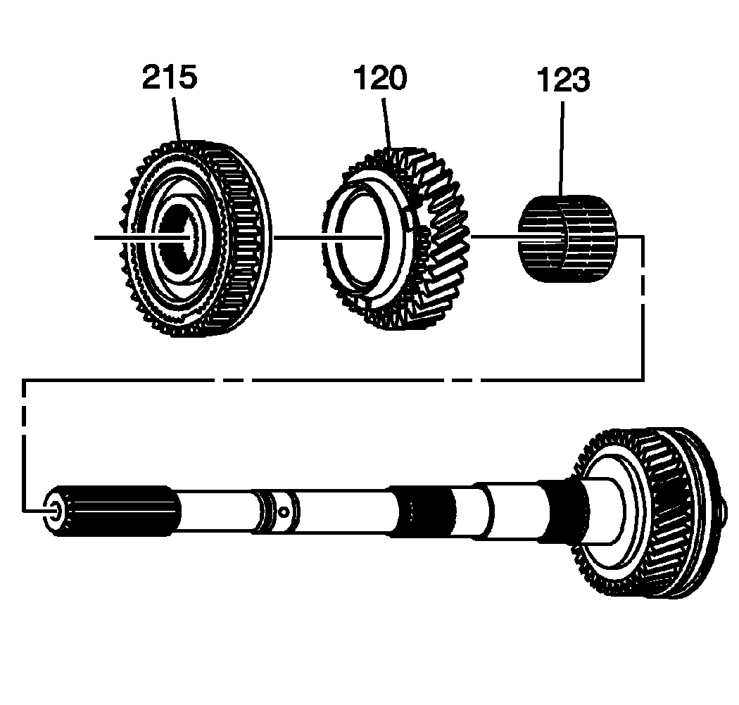
- Remove the following components from the rear of the output shaft:
- The 1st/2nd gear synchronizer hub assembly (215)
- The 2nd gear (120)
- The 2nd gear bearing (123)
- Using J 8001-3:
indicator or J 26900-12:
indicator (1) and J 26900-13:
base (2), measure the 3rd gear axial play.
- Standard Clearance: 0.10-0.25 mm (0.0039-0.0098 in)
- Maximum Clearance: 0.30 mm (0.0118 in)
- Position J 8001-3: indicator or J 26900-12: indicator (1) on the top of the gear teeth.
- Zero the gauge.
- Lift up on the gear to measure the clearance.
- If the clearance exceeds the maximum, refer to Gears and Shafts Cleaning and Inspection .
- Remove the 3rd/4th gear synchronizer hub retaining ring.
- Install the J 22912-B: plates (2) with the J 45869: plates (1) under the 3rd gear.
- Using a hydraulic press, remove the 3rd/4th gear synchronizer hub.
- Remove the following components from the front of the output shaft:
- The 3rd/4th gear synchronizer hub assembly (235)
- The 3rd gear (130)
- The 3rd gear bearing (133)
 Courtesy of GENERAL MOTORS CORP.
NOTE:
The following steps apply to both the 4WD and the RWD transmission, except where noted.
NOTE:
Before disassembly of the output shaft, measure the axial play of the speed gears. If axial play of the speed gears is incorrect, it may cause shifting concerns or transmission noise.


CAUTION:
Protect the speed gear teeth when removing the synchronizer hubs to prevent damage to the gear.

NOTE:
The 3rd/4th gear synchronizer hub cannot be used again if removed. A new hub is required for assembly.

CAUTION:
Protect the speed gear teeth when removing the synchronizer hubs to prevent damage to the gear.
