Shift Shaft and Shift Fork Cleaning and Inspection
WARNING: This page is about a different variant/trim than selected.
- Clean all of the shift parts in a suitable cleaning solvent and air dry the parts.
- Roll the shift shafts on a flat surface to inspect them for being bent.
- Inspect the shift shafts for wear or scoring.
- If light scoring is present, dress the area using a soft stone. Do not use a file.
- Inspect the roll pin in the shift shaft gate (b) for being loose.
- Inspect the gates (a) for damage or wear.
- Inspect the shift shaft detents (c) for excessive rounding, chipping or distortion.
- Replace the shift shaft if faulty.
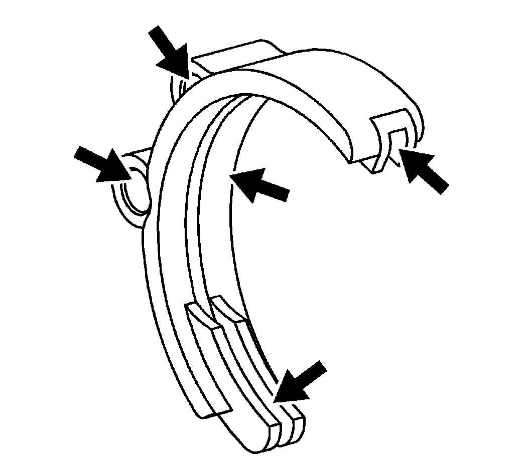
- Inspect the 1st/2nd shift fork for scoring, distortion, or wear through the hardened surface.
- Inspect for a bent shift fork.
- Inspect for cracks in the shift fork.
- Inspect the shift rail holes for excessive wear.
- Replace the shift fork if faulty.
- Using a feeler gauge, measure the clearance between the reverse gear and the shift fork.
Specification: Maximum Clearance: 1.0 mm (0.039 in)
- If the clearance exceeds the maximum, replace the shift fork or the reverse gear.
- Inspect the 3rd/4th shift fork for scoring, distortion, or wear through the hardened surface.
- Inspect for a bent shift fork.
- Inspect for cracks in the shift fork.
- Inspect the shift rail hole for excessive wear.
- Replace the shift fork if faulty.
- Using a feeler gauge, measure the clearance between the 3rd/4th synchronizer sleeve and the shift fork.
Specification: Maximum Clearance: 1.0 mm (0.039 in)
- If the clearance exceeds the maximum, replace the shift fork or the sleeve.
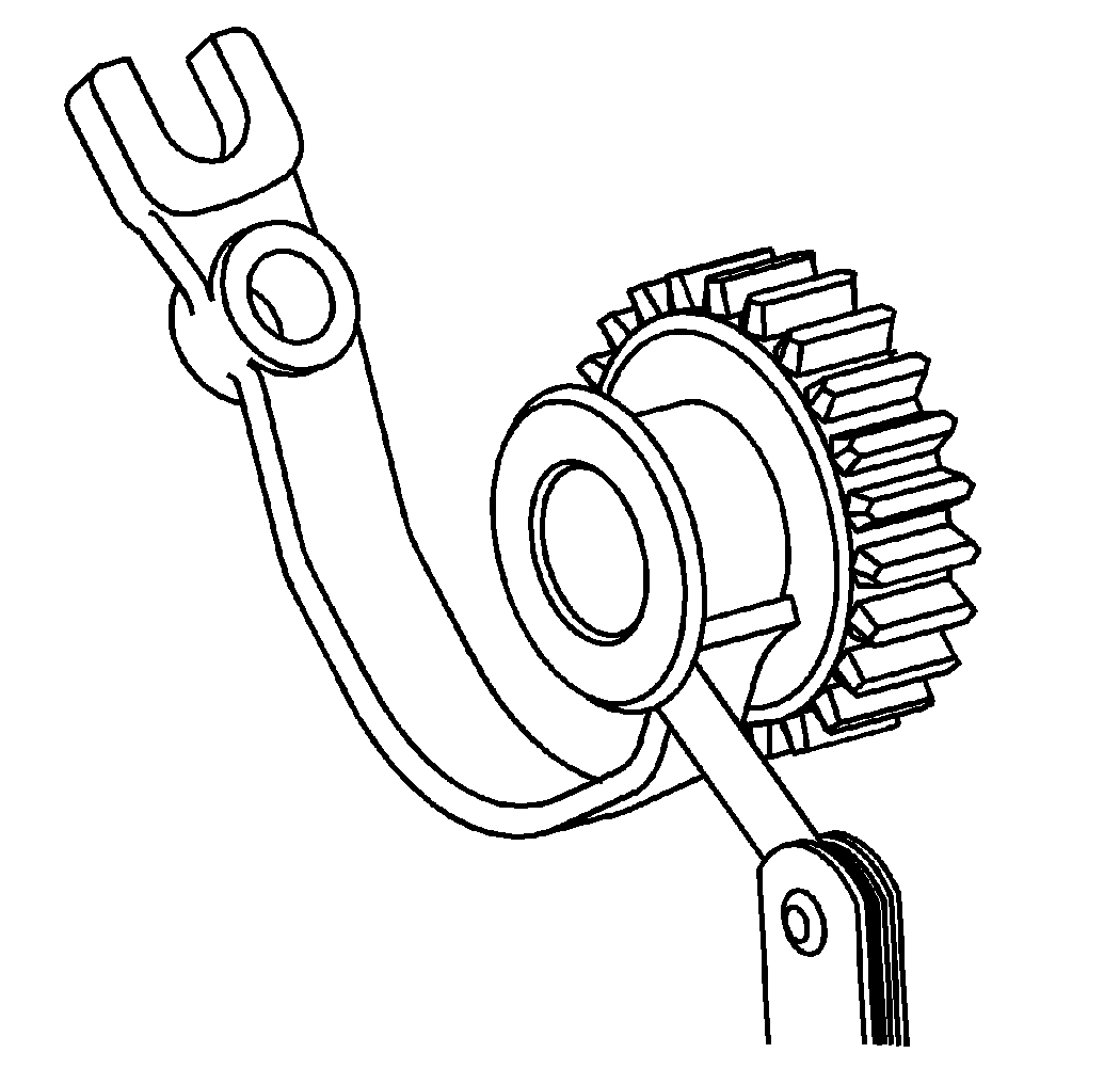
- Inspect the reverse shift fork and the reverse shift lever for wear or damage.
- Replace the reverse shift fork or the reverse shift lever if found faulty.
- Using a feeler gauge, measure the clearance between the reverse idler gear and the reverse shift fork.
Specification:
- Standard Clearance: 0.05-0.35 mm (0.0020-0.0138 in)
- Maximum clearance: 0.50 mm (0.0197 in)
- If the clearance exceeds the maximum, replace the shift fork or the reverse idler gear.
- Inspect the 5th gear shift fork for worn pads.
- Inspect for a bent shift fork.
- Inspect for cracks in the shift fork.
- Inspect the shift rail hole for excessive wear.
- Inspect the shift fork gates for excessive wear.
- Replace the shift fork if faulty.
- Using a feeler gauge, measure the clearance between the 5th synchronizer sleeve and the shift fork.
Specification: Maximum Clearance: 1.0 mm (0.039 in)
- If the clearance exceeds the maximum, replace the shift fork or the sleeve.
- Inspect the interlocks for excessive wear.
- Inspect the detent springs for distortion.
- Inspect the shift detent balls for wear.
- Replace the faulty parts.
- Roll the shift control shaft on a flat surface to inspect it for being bent.
- Inspect the shaft for wear or scoring.
- If light scoring is present, dress the area using a soft stone. Do not use a file.
- Inspect the shift control shaft for wear at the control lever.
- Replace the shift control shaft if faulty.
- Inspect the internal shift control lever for damage or excessive wear.
- Replace the internal shift control lever if faulty.


 Courtesy of GENERAL MOTORS CORP.
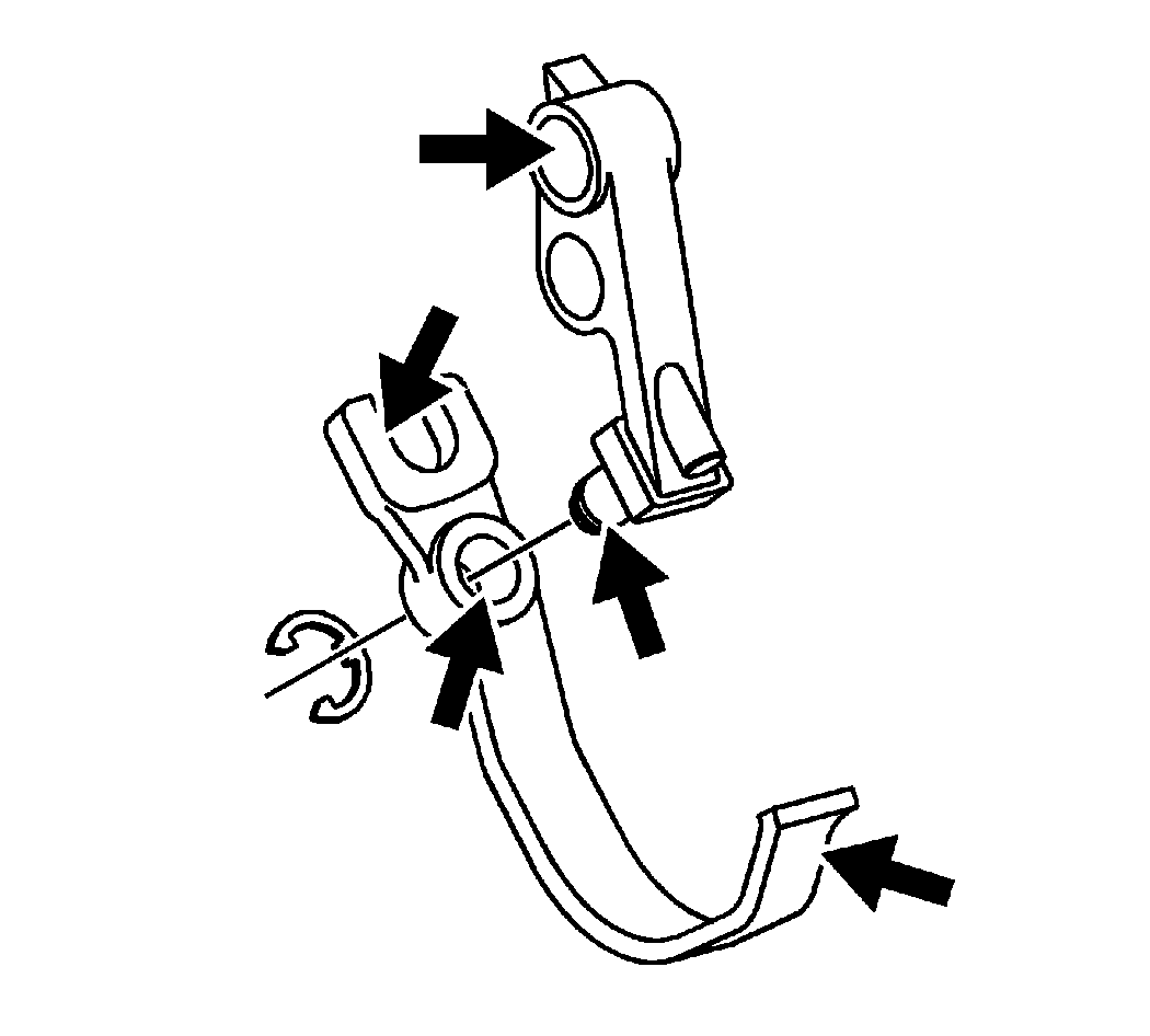
 Courtesy of GENERAL MOTORS CORP.
 Courtesy of GENERAL MOTORS CORP.
