MMI Radio Most (I8D), Through My 2016
Information Electronics Control Module 1 J794

- Connection, AM/FM1/FM2
- DAB connection from Digital Radio Antenna -R183-
- 4-Pin Connector -T4al- to the Front Information Display Control Head -J685-
- 4-Pin Connector -T4w- to the External Audio Source Connection -R199-
- GPS connection from Roof Antenna -R216-
- MOST Bus
- Connection Block with Four Multi-Pin Connectors
Only North America, I8D and QV3
- Connection, AM/FM1/FM2
- SDARS connection from Satellite Tuner Antenna -R172-
- 4-Pin Connector -T4al- to the Front Information Display Control Head -J685-
- 4-Pin Connector -T4w- to the External Audio Source Connection -R199-
- GPS connection from Roof Antenna -R216-
- MOST Bus
- Connection Block with Four Multi-Pin Connectors
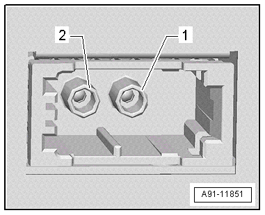
1 - AM/FM1/FM2 antenna connection

- Connector 2, AM/FM1 from Antenna Amplifier -R24-, Antenna -R11-
- Connector 1, FM2 from Antenna Amplifier 2 -R111- or Antenna Amplifier 3 -R112-, Radio Antenna 2 -R93-
Unlisted connector terminals are not assigned.
3 - 4-Pin Connector T4al

All pins are connected to the Front Information Display Control Head -J685-.
- LVDS (-)
- Not Assigned
- LVDS (+)
- Ground
4 - 4-Pin Connector T4w
All pins are connected to the External Audio Source Connection -R199-.
- D (+)
- iPod Detected
- D (-)
- Ground
6 - MOST bus
- Input
- Output
7 - Connection block with four multi-pin connectors
A - 8-Pin Connector T8ag

- Right Rear Speaker (+)
- Right Front Speaker (+)
- Left Front Speaker (+)
- Left Rear Speaker (+)
- Right Rear Speaker (-)
- Right Front Speaker (-)
- Left Front Speaker (-)
- Left Rear Speaker (-)
B - 12-Pin Connector T12x
- Microphone input (+) from Microphone Unit In Front Roof Module -R164-, Telephone Microphone -R38-
- Not Assigned
- Not Assigned
- LF (+)
- LF mute
- CVBS cable (-) from Rearview Camera System Control Module -J772-
- Microphone input (-) from Microphone Unit In Front Roof Module -R164-, Telephone Microphone -R38-
- Not Assigned
- Not Assigned
- LF (-)
- Not Assigned
- CVBS cable (+) from Rearview Camera System Control Module -J772-
C - 12-Pin Connector T12y
All pins are connected to the External Audio Source Connection -R199-.
- LF-In Ground
- Right LF-In
- USB, +5 V
- USB, Ground
- iPod, ACC Power
- Detect
- Left LF-In
- LF-In ground shielding
- CVBS cable (+)
- CVBS cable (-)
- iPod Data
- iPod Data
D - 8-Pin Connector T8j
9 - Subwoofer -R211- (+)
10 - Center Speaker -R208- (+)
13 - Subwoofer -R211- (-)
14 - Center Speaker -R208- (-)
17 - Terminal 31
18 - Terminal 30
E - 12-Pin Connector T12w
- CAN bus high to the Multimedia System Control Head -E380- /Front Information Display Control Head -J685-
- Reset Multimedia System Control Head -E380-
- Ring-Break Diagnostic Cable
- Not Assigned
- Switch-On Signal to Telephone Baseplate -R126-
- CAN bus high, Infotainment
- CAN bus low to the Multimedia System Control Head -E380- /Front Information Display Control Head -J685-
- Reset Information Electronics Control Module 1 -J794-) from Multimedia System Control Head -E380-
- Not Assigned
- Not Assigned
- Status signal from Telephone Baseplate -R126-
- CAN bus low, Infotainment