Hydraulic Impulse Storage (If Fitted)

| ITEM | DESCRIPTION |
|---|---|
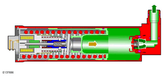
| 1 | Solenoid |
| 2 | Magnetic core |
| 3 | Keeper |
| 4 | Balls |
| 5 | Piston spring |
| 6 | Accumulator cylinder |
| 7 | Piston |
| 8 | One-way restrictor |
| 9 | Inlet/outlet port |
| 10 | Piston ATF volume |
| 11 | Keeper spring |
| 12 | Electrical connector |
The Hydraulic Impulse Storage (HIS) system if fitted to vehicles with the auto stop/start system.
The HIS system comprises a cylindrical accumulator which contains an electro-mechanical locking unit, a spring actuated piston and a one-way restrictor. The accumulator is located at the rear of the Mechatronic valve block and is secured in position with three screws and sealed into a port in the transmission casing with an O-ring seal.
The electro-mechanical locking unit comprises a low-current solenoid, a spring loaded keeper incorporating a magnetic core and a number of balls. The keeper has a detent into which the balls locate during filling of the HIS when the engine is running and the Automatic Transmission Fluid (ATF) pump is producing pressure.
The one-way restrictor is located in the inlet/outlet port of the accumulator. The restrictor provides a controlled charging of the HIS, to allow a small volume flow of ATF. This ensures that the operation of the transmission shift elements are not compromised by a sudden drop in ATF pressure. The restrictor allows a charging time for the HIS of approximately 5 seconds. When discharge is required, the restrictor allows full flow from the cylinder.
The filling process for the HIS has several steps:
- When the engine is running and the ATF pump is producing pressure, the one-way restrictor allows a controlled flow of ATF which acts on the piston.
- The ATF pressure moves the piston into the accumulator cylinder. A locking ring on the piston passes over the balls which are at this point located in the keeper detent.
- As the piston continues to move, a spring in the center of the keeper moves the locking cylinder and the magnetic core towards the solenoid windings and into the final fully charged position. The energized solenoid holds the magnetic core and the balls are lifted from the detent by the movement of the keeper, locking the piston in the charged position. The HIS is now electro-mechanically locked and ready for an engine stop to occur.
- When the engine is stopped, the ATF pump also stops and ATF pressure is decayed. The pressure acting on the piston is also decayed and the piston moves to be held in the locked position by the balls. The energy required for hydraulic filling during engine start is now stored in the tensioned piston spring. The solenoid remains energized to hold the keeper in position and the balls out of the detent to lock the piston.
Charging

Charged

Engine start process:
- When the engine is restarted, the solenoid holding current is removed, which starts the unlocking process.
- The magnetic core is released and the keeper is moved towards the piston under spring pressure. The balls fall into the detent in the keeper, releasing the piston.
- The piston is moved under spring pressure, pushing out the volume of ATF. The one-way restrictor opens fully to allow unrestricted flow of ATF from the accumulator cylinder into the transmission housing. The process is completed between 300 and 350 ms.
- Once the engine is started, the ATF pump produces flow and pressure to provide seamless transmission shift element engagement as soon as the engine is started.
Discharging