After-Run Coolant Pump, Coolant Shut-Off Valve, Air Quality Sensor, Rear Window Defogger: Notes
- Outside Air Temperature Sensor -G17-
- To check, use the :Vehicle Diagnostic Tester
in the "Guided Fault Finding"
function. Refer to the appropriate Wiring Diagram(s). NOTE:
The Vehicle Electrical System Control Module -J519- evaluates the measured value for the Outside Air Temperature Sensor -G17-.
- Removing and Installing. Refer to OUTSIDE AIR TEMPERATURE SENSOR -G17-, REMOVING AND INSTALLING .
- To check, use the :Vehicle Diagnostic Tester
in the "Guided Fault Finding"
function. Refer to the appropriate Wiring Diagram(s).
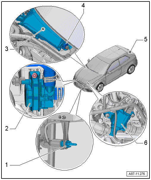
- After-Run Coolant Pump -V51-
- Shown on a 1.4 L TFSI engine
- Installed in the coolant circuit depending on the engine version. Refer to COOLING SYSTEM/COOLANT [CRUA, DEJA] / COOLANT SYSTEM/COOLANT [CNSB, CNTC] (Connection Diagram for Coolant Hoses) and the appropriate Wiring Diagram(s).
- Activated by the engine control module by the request from the A/C Control Module -J301- /Climatronic Control Module -J255- control head.
- Also serves as support for the engine coolant pump to improve the coolant flow rate through the heater core for the heater to increase the heating output at certain engine speeds.
- Removing and installing. Refer to COOLANT PUMP/COOLANT THERMOSTAT [CNSB, CNTC] / COOLANT PUMP/THERMOSTAT [CRUA, DEJA] / ELECTRIC COOLANT PUMP, REMOVING AND INSTALLING [CNSB, CNTC] / ELECTRIC COOLANT PUMP, REMOVING AND INSTALLING [CRUA, DEJA] (Overview - Electrical Coolant Pump).
- Fresh Air Intake
- Removing and Installing. Refer to FRESH AIR INTAKE, REMOVING AND INSTALLING
.NOTE:
Depending on the vehicle version, a dust filter may also be installed instead of an intake grille (introduction not yet finalized).
- Removing and Installing. Refer to FRESH AIR INTAKE, REMOVING AND INSTALLING
.
- Air Quality Sensor -G238- with Humidity Sensor In Fresh Air Intake Duct -G657-
- Only on vehicles with an automatic climate control system
- To check, use the Vehicle Diagnostic Tester in the "Guided Fault Finding" function. Refer to the appropriate Wiring Diagram(s).
- Removing and Installing. Refer to AIR QUALITY SENSOR -G238- /HUMIDITY SENSOR IN FRESH AIR INTAKE DUCT -G657-, REMOVING AND INSTALLING .
- Rear Window Defogger -Z1-
- Notes on function of the rear window defogger. Refer to REAR WINDOW DEFOGGER .
- Check the activation and function of the rear window defogger using the Vehicle Diagnostic Tester in "Guided Fault Finding" function and refer to the appropriate Wiring Diagram(s).
- Coolant Shut-Off Valve -N82-
- Shown on a 1.8L TFSI engine
- Installed in the coolant circuit depending on the engine version. Refer to COOLING SYSTEM/COOLANT [CRUA, DEJA] / COOLANT SYSTEM/COOLANT [CNSB, CNTC] (Connection Diagram for Coolant Hoses) and the appropriate Wiring Diagram(s).
- Activated by the engine control module after approval of the A/C Control Module -J301- /Climatronic Control Module -J255- control head.
- Depending on the setting on the A/C Control Module -J301- /Climatronic Control Module -J255- control head, it blocks the coolant flow through the heater core for the heater when the engine is cold, for example, to accelerate the engine warming up when the A/C system is switched off.
- Removing and Installing. Refer to COOLING SYSTEM/COOLANT [CRUA, DEJA] / COOLANT SYSTEM/COOLANT [CNSB, CNTC] (Connection Diagram for Coolant Hoses).