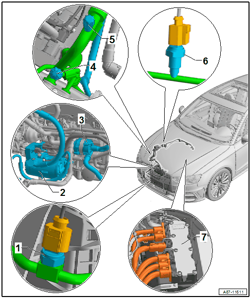
Additional (And On The A3 E-Tron Installed Differently) Components On Vehicles With A High-Voltage System (A3 E-Tron).

- High-Voltage Heater (PTC) -Z115- (with High-Voltage Heater (PTC) Control Module -J848-)
- Pay attention to any additional warning messages for all procedures on the High-Voltage Heater (PTC) -Z115- (and on vehicles with a high-voltage system). Refer to SAFETY PRECAUTIONS WHEN WORKING ON VEHICLES WITH HIGH-VOLTAGE SYSTEM and WORKING ON VEHICLES WITH HIGH-VOLTAGE SYSTEM (HYBRID VEHICLES) .
- To check, use the Vehicle Diagnostic Tester in the "Guided Fault Finding" function. Refer to the appropriate Wiring Diagram(s).
- Removing and Installing. Refer to HIGH-VOLTAGE HEATER (PTC) -Z115- (WITH HIGH-VOLTAGE HEATER (PTC) CONTROL MODULE -J848-), REMOVING AND INSTALLING .
- Connecting the High-Voltage Heater (PTC) -Z115- in the coolant circuit to the heater core. Refer to HIGH VOLTAGE HEATER (PTC) -Z115-, INCORPORATION, IN THE COOLANT CIRCUIT .
- Coolant Change-Over Valve 2 -N633-
- Removing and installing. Refer to COOLANT CHANGE-OVER VALVE 2 -N633-, REMOVING AND INSTALLING and COOLANT VALVES, REMOVING AND INSTALLING (N82 & N488) [CNSB, CNTC] / COOLANT VALVES, REMOVING AND INSTALLING [CNSB, CNTC] / COOLANT PUMP/THERMOSTAT [CRUA, DEJA] .
- Coolant Change-Over Valve 2 -N633- Function and Activation, Checking. Use the Vehicle Diagnostic Tester in the "Guided Fault Finding" function (for the engine). Refer to COOLANT PUMP/COOLANT THERMOSTAT [CNSB, CNTC] / COOLANT PUMP/THERMOSTAT [CRUA, DEJA] and the appropriate Wiring Diagram(s).
- Checking the incorporation of the Coolant Change-Over Valve 2 -N633- in the engine coolant circuit. Refer to HIGH VOLTAGE HEATER (PTC) -Z115-, INCORPORATION, IN THE COOLANT CIRCUIT
and COOLANT PUMP/COOLANT THERMOSTAT [CNSB, CNTC]
/ COOLANT PUMP/THERMOSTAT [CRUA, DEJA]
.NOTE:
The Coolant Change-Over Valve 2 -N633- is activated by the respective engine control module (for example, by the Engine Control Module -J623-) when the A/C system requests heating output and the vehicle is in electric driving mode or the "parking air conditioner" function is active. Refer to PARKING AIR CONDITIONER , the appropriate Wiring Diagram(s) and use the Vehicle Diagnostic Tester in the "Guided Fault Finding " function.
If there is a complaint regarding insufficient heating output of the A/C system when the engine off and / or when the engine running, regardless of whether the High-Voltage Heater (PTC) -Z115- is activated, check that it is installed on the proper side and it is functioning correctly. Refer to the appropriate Wiring Diagram(s). and use the Vehicle Diagnostic Tester in the "Guided Fault Finding" function.
In order for the coolant warmed by the High-Voltage Heater (PTC) -Z115- to be delivered through the heater core, the High Temperature Circuit Coolant Pump -V467- and the Transmission Coolant Valve -N488- must also be activated (by the respective engine control module). So that the coolant flows in the correct direction, the check valves in the coolant circuit must also be installed correctly and their function must be OK. For more information. Refer to HIGH VOLTAGE HEATER (PTC) -Z115-, INCORPORATION, IN THE COOLANT CIRCUIT , PARKING AIR CONDITIONER , the appropriate Wiring Diagram(s). and COOLING SYSTEM/COOLANT [CRUA, DEJA] / COOLANT SYSTEM/COOLANT [CNSB, CNTC] (Connection Diagram for Coolant Hoses). Use the Vehicle Diagnostic Tester in the "Guided Fault Finding" function).
- Coolant Change-Over Valve 1 -N632-
- Removing and Installing. Refer to COOLANT CHANGE-OVER VALVE 1 -N632-, REMOVING AND INSTALLING and [For engine(s) CNSB, CNTC] Cooling System[For engine(s) CRUA, DEJA] Cooling System[For engine(s) CNSB, CNTC] Cooling System .
- Coolant Change-Over Valve 1 -N632- Function and Activation, Checking. Use the Vehicle Diagnostic Tester in the "Guided Fault Finding" function (for the engine). Refer to COOLANT PUMP/COOLANT THERMOSTAT [CNSB, CNTC] / COOLANT PUMP/THERMOSTAT [CRUA, DEJA] and the appropriate Wiring Diagram(s).
- Check the incorporation of the Coolant Change-Over Valve 1 -N632- in the coolant circuit of the high-voltage system. Refer to COOLING SYSTEM/COOLANT [CRUA, DEJA]
/ COOLANT SYSTEM/COOLANT [CNSB, CNTC]
(Connection Diagram for Coolant Hoses - High-Voltage System Cooling Components).NOTE:
The Coolant Change-Over Valve 1 -N632- is activated by the respective engine control module (for example, by the Engine Control Module -J623-), when it is necessary to cool the Electric Drive Power and Control Electronics -JX1- or the High-Voltage Battery Charger Control Module -J1050-. For more information. Refer to the appropriate Wiring Diagram(s) and COOLING SYSTEM/COOLANT [CRUA, DEJA] / COOLANT SYSTEM/COOLANT [CNSB, CNTC] (Connection Diagram for Coolant Hoses - High-Voltage System Cooling Components). Use the Vehicle Diagnostic Tester in the "Guided Fault Finding" function.
- High-Voltage Battery Heater Core Refrigerant Shut-Off Valve -N542-
- To check, use the Vehicle Diagnostic Tester in the "Guided Fault Finding" function. Refer to the appropriate Wiring Diagram(s).
- Removing and Installing. Refer to HIGH VOLTAGE BATTERY HEATER CORE REFRIGERANT CUT-OFF VALVE -N542-, REMOVING AND INSTALLING .
- Further information. Refer to SYSTEM OVERVIEW - REFRIGERANT CIRCUIT, VEHICLES WITH HIGH VOLTAGE SYSTEM .
- Refrigerant Line with Restrictor
- A constriction (restrictor) is installed in this refrigerant line. Refer to REFRIGERANT LINE WITH RESTRICTOR .
- To remove, remove the High-Voltage Battery Heater Core Refrigerant Shut-Off Valve -N542- (refer to HIGH VOLTAGE BATTERY HEATER CORE REFRIGERANT CUT-OFF VALVE -N542-, REMOVING AND INSTALLING ) and remove the refrigerant line from the High-Voltage Battery Heat Exchanger (refer to HIGH VOLTAGE BATTERY HEAT EXCHANGER, REMOVING AND INSTALLING
).NOTE:
The diameter of the bore is approximately 0.7 mm. Depending on the version of the refrigerant line, this constriction is either permanently installed in the refrigerant line or is only inserted. A screen to separate floating deposits may be installed on the inserted version, which can block the restrictor hole.
The restrictor limits the refrigerant flow to the high-voltage battery heat exchanger with an open High-Voltage Battery Heater Core Refrigerant Shut-Off Valve -N542- (and with this its cooling output).
- High-Voltage Battery Heat Exchanger
- To check, use the Vehicle Diagnostic Tester in the "Guided Fault Finding" function. Refer to the appropriate Wiring Diagram(s).
- Removing and Installing. Refer to HIGH VOLTAGE BATTERY HEAT EXCHANGER, REMOVING AND INSTALLING .
- Further information. Refer to SYSTEM OVERVIEW - REFRIGERANT CIRCUIT, VEHICLES WITH HIGH VOLTAGE SYSTEM .
- Heater and A/C Unit Refrigerant Shut-Off Valve -N541-
- To check, use the Vehicle Diagnostic Tester in the "Guided Fault Finding" function. Refer to COOLING OUTPUT, CHECKING, VEHICLES WITH AUTOMATIC CLIMATE CONTROL SYSTEM (WITH HIGH VOLTAGE SYSTEM) and the appropriate Wiring Diagram(s).
- Removing and Installing. Refer to HEATER AND A/C UNIT REFRIGERANT CUT-OFF VALVE -N541-, REMOVING AND INSTALLING .
- Further information. Refer to SYSTEM OVERVIEW - REFRIGERANT CIRCUIT, VEHICLES WITH HIGH VOLTAGE SYSTEM .
- High-Voltage Battery Coolant Valve -N688-
- Removing and Installing. Refer to HIGH VOLTAGE BATTERY COOLANT VALVE -N688-, REMOVING AND INSTALLING and COOLANT VALVES, REMOVING AND INSTALLING (N82 & N488) [CNSB, CNTC] / COOLANT VALVES, REMOVING AND INSTALLING [CNSB, CNTC] .
- Check the incorporation of the high-voltage battery heat exchanger (chiller), the High-Voltage Battery Coolant Pump -V590- and the High-Voltage Battery Coolant Valve -N688- in the coolant circuit of the high-voltage system. Refer to HIGH VOLTAGE BATTERY HEAT EXCHANGER IN THE HIGH VOLTAGE SYSTEM COOLANT CIRCUIT, INCORPORATION and COOLING SYSTEM/COOLANT [CRUA, DEJA] / COOLANT SYSTEM/COOLANT [CNSB, CNTC] (Connection Diagram for Coolant Hoses - High-Voltage System Cooling Components).
- Check the function and activation of the High-Voltage Battery Coolant Pump -V590- and the High-Voltage Battery Coolant Valve -N688- using the Vehicle Diagnostic Tester in the "Guided Fault Finding" function (for the hybrid battery management system). Refer to COOLING SYSTEM/COOLANT [CRUA, DEJA] / COOLANT SYSTEM/COOLANT [CNSB, CNTC] (Connection Diagram for Coolant Hoses - High-Voltage System Cooling Components).
- A/C Pressure/Temperature Sensor -G395-
- To check, use the Vehicle Diagnostic Tester in the "Guided Fault Finding" function. Refer to the appropriate Wiring Diagram(s).
- Only installed on specific versions (for example vehicles for North America).
- Overview, electrically-driven A/C compressor, refrigerant line. high-voltage battery heat exchanger (on vehicles with a high-voltage system) OVERVIEW, ELECTRICALLY-DRIVEN A/C COMPRESSOR, REFRIGERANT LINE. HIGH-VOLTAGE BATTERY HEAT EXCHANGER (ON VEHICLES WITH A HIGH-VOLTAGE SYSTEM). .
- Further information. Refer to SYSTEM OVERVIEW - REFRIGERANT CIRCUIT, VEHICLES WITH HIGH VOLTAGE SYSTEM .
- Electrically-Driven A/C Compressor
- With A/C Compressor Control Module -J842- and Electrical A/C Compressor -V470-
- Pay attention to any additional warning messages for all procedures on the Electrical A/C Compressor -V470- (and on vehicles with a high-voltage system). Refer to SAFETY PRECAUTIONS WHEN WORKING ON VEHICLES WITH HIGH-VOLTAGE SYSTEM and WORKING ON VEHICLES WITH HIGH-VOLTAGE SYSTEM (HYBRID VEHICLES) .
- Removing and Installing. Refer to ELECTRICALLY-POWERED A/C COMPRESSOR, REMOVING AND INSTALLING .
- Refer to OVERVIEW - A/C COMPRESSOR POWER UNIT, ELECTRICALLY-DRIVEN A/C COMPRESSOR
- There are different versions (for example, for vehicles for Europe or NAR). Refer to the Parts Information and use the Vehicle Diagnostic Tester in the "Guided Fault Finding" function.
- There are different versions depending on the refrigerant (R134a or R1234yf).
- Further information. Refer to SYSTEM OVERVIEW - REFRIGERANT CIRCUIT, VEHICLES WITH HIGH VOLTAGE SYSTEM .NOTE:
The Electrical A/C Compressor -V470- is supplied with electric energy via a fuse installed in the Electric Drive Power and Control Electronics -JX1-. Refer to ELECTRICAL A/C COMPRESSOR FUSE, REMOVING AND INSTALLING , appropriate service information and the appropriate Wiring Diagram(s).
- High Temperature Circuit Coolant Pump -V467-
- Removing and installing. Refer to COOLANT PUMP/COOLANT THERMOSTAT [CNSB, CNTC] / COOLANT PUMP/THERMOSTAT [CRUA, DEJA] / COOLANT THERMOSTAT, CHECKING [CRUA, DEJA] .
- Checking the incorporation of the High Temperature Circuit Coolant Pump -V467- in the engine coolant circuit. Refer to COOLING SYSTEM/COOLANT [CRUA, DEJA] / COOLANT SYSTEM/COOLANT [CNSB, CNTC] .
- Check the function and activation of the High Temperature Circuit Coolant Pump -V467- and the Coolant Change-Over Valve 2 -N633- using the Vehicle Diagnostic Tester in the "Guided Fault Finding" function. Refer to the appropriate Wiring Diagram(s).
- More information. Refer to -Item 2-.
- High Pressure Side Service Connection
- For measuring, discharging and chargingCAUTION:
Danger due to refrigerant coming out under pressure when there is a faulty valve in the refrigerant circuit.
Danger of frost bite to skin and other parts of the body.
- Only remove when the refrigerant circuit is empty; the connection is without a valve. Refer to A/C SYSTEM, GENERAL INFORMATION (R134a) or SYSTEM OVERVIEW - REFRIGERANT CIRCUIT / REFRIGERANT CIRCUIT (R1234yf) / REFRIGERANT CIRCUIT (R134a) .
- Overview. Refer to OVERVIEW - CONDENSER, A/C COMPRESSOR, REFRIGERANT LINES AND EXPANSION VALVE .
- There are different versions depending on the refrigerant (R134a or R1234yf). Refer to SERVICE CONNECTION DIFFERENCES, DEPENDING ON REFRIGERANT (R134A OR R1234YF) .
- For measuring, discharging and charging
- Low Pressure Side Service Connection
- For measuring and dischargingCAUTION:
Danger due to refrigerant coming out under pressure when there is a faulty valve in the refrigerant circuit.
Danger of frost bite to skin and other parts of the body.
- Only remove when the refrigerant circuit is empty; the connection is without a valve. Refer to A/C SYSTEM, GENERAL INFORMATION (R134a) or SYSTEM OVERVIEW - REFRIGERANT CIRCUIT / REFRIGERANT CIRCUIT (R1234yf) / REFRIGERANT CIRCUIT (R134a) .
- Overview. Refer to OVERVIEW - CONDENSER, A/C COMPRESSOR, REFRIGERANT LINES AND EXPANSION VALVE .
- There are different versions depending on the refrigerant (R134a or R1234yf). Refer to SERVICE CONNECTION DIFFERENCES, DEPENDING ON REFRIGERANT (R134A OR R1234YF) .
- For measuring and discharging
- Refrigerant Circuit Pressure Sensor -G805-
- To check, use the Vehicle Diagnostic Tester in the "Guided Fault Finding" function. Refer to the appropriate Wiring Diagram(s).
- Overview. Refer to OVERVIEW - CONDENSER, A/C COMPRESSOR, REFRIGERANT LINES AND EXPANSION VALVE .
- Removing and Installing. Refer to REFRIGERANT CIRCUIT PRESSURE SENSOR -G805-, REMOVING AND INSTALLING .
- Only installed on specific version (not installed for example in vehicles for North America). Refer to the Parts Information and Vehicle Diagnostic Tester in the "Guided Fault Finding" function.
- Further information. Refer to SYSTEM OVERVIEW - REFRIGERANT CIRCUIT, VEHICLES WITH HIGH VOLTAGE SYSTEM .
- Electric Drive Power and Control Electronics -JX1-
- With fuse to protect the energy supply of the Electrical A/C Compressor -V470-. Refer to ELECTRICAL A/C COMPRESSOR FUSE, REMOVING AND INSTALLING and the appropriate Wiring Diagram(s).
- Removing and Installing. Refer to ELECTRICAL A/C COMPRESSOR FUSE, REMOVING AND INSTALLING and appropriate service information .
- Check using the Vehicle Diagnostic Tester in the "Guided Fault Finding"
function for A/C system and battery regulation.NOTE:
The Electrical A/C Compressor -V470- is supplied with electric energy via a fuse installed in the Electric Drive Power and Control Electronics -JX1-.