Rear Headliner Vent Poor Performance (JLRTB02119NAS3)
Reference number: JLRTB02119NAS3
Supersedes refnos: JLRTB02119NAS1
REAR HEADLINER VENT POOR PERFORMANCE
TECHNICAL SERVICE BULLETIN
| LAND ROVER: | All Models |
| SECTION: | 412-02 |
CONDITION SUMMARY
SITUATION
The air passing through the rear right headliner air vent is approximately 12°C (53 degrees Fahrenheit) higher than the air passing through the rear left headliner air vent.
This bulletin has been updated due to changes to the affected Vehicle Identification Number (VIN) range.
CAUSE:
Excessive increase in air temperature within the air ducts, caused by the current air duct routing and insufficient insulation.
ACTION:
Follow the instructions below.
Check the VIN in the warranty portal, if the bulletin JLRTB02119 has previously been completed DO NOT continue. Repair the vehicle as necessary with reference to TOPIx. Check the part numbers of the air ducts installed to the vehicle (refer to the parts section of this bulletin) before ordering new parts. If the new level of parts are already installed, check that the ducts have been correctly assembled, that there is no obvious leakage from the joints and that there are no blockages within the ducting.
PARTS
| PART NUMBER | DESCRIPTION | QUANTITY |
|---|---|---|
| Vehicles with 5 seats only | ||
| LR185930 | Air duct | 1 |
| LR185931 | Air duct | 1 |
| LR185932 | Air duct | 1 |
| LR185933 | Air duct | 1 |
| LR185934 | Air duct | 1 |
| LR185935 | Air duct | 1 |
| LR185936 | Air duct | 1 |
| Vehicles with 7 seats only | ||
| 568123459 | Air duct | 1 |
| 568123460 | Air duct | 1 |
| 568123461 | Air duct | 1 |
| 568123462 | Air duct | 1 |
| 568123463 | Air duct | 1 |
| 568123464 | Air duct | 1 |
| 568123465 | Air duct | 1 |
| 568123466 | Air duct | 1 |
WARRANTY
- Repair procedures are under constant review, and therefore times are subject to change; those quoted here must be taken as guidance only. Use TOPIx to obtain the latest repair time.
- The JLR claims submission system requires the use of causal part numbers. Labor only claims must show the causal part number with a quantity of zero.
| DESCRIPTION | SRO | TIME (HOURS) | CONDITION CODE | CAUSAL PART |
|---|---|---|---|---|
| JLRTB - Without third row seating - Rear air ducts - Renew | 99.01.95 | 3.0 | * | LR153633 |
| JLRTB - With third row seating - Rear air ducts - Renew | 99.01.94 | 3.3 | * | LR153633 |
SERVICE INFORMATION
- Some variation in the illustrations may occur, but the essential information is always correct.
- Some components shown removed for clarity.
The illustration shows the 6 right air ducts which require removal.
- Right air duct 1.
- Right air duct 2.
- Right air duct 3.
- Right air duct 4.
- Right air duct 5.
- Right air duct 6.
The illustration shows the 3 left air ducts which require removal.
- Left air duct 1.
-
NOTE: Left air duct 2 will be removed during completion of the 'Headliner Lower For Access' procedure.
Left air duct 2.
- Left air duct 3.


LEFT AND RIGHT AIR DUCT REMOVAL
- Some variation in the illustrations may occur, but the essential information is always correct.
- Some components shown removed for clarity.
All vehicles
-
NOTE: Left air duct 2 will be removed during completion of the 'Headliner Lower For Access' procedure.
Lower the headliner for access only, (see TOPIx Workshop Manual section 501-05: Interior Trim And Ornamentation - Removal and Installation - Headliner Lower For Access).
Vehicles with 5 seats only
Remove the loadspace floor trim.
- Release the latch.
- Remove the loadspace floor trim.
- Remove the right loadspace trim panel, (see TOPIx Workshop Manual section 501-05: Interior Trim And Ornamentation - Removal and Installation - Right Loadspace Trim Panel - Vehicles With: 5 Seats/executive Seats).
Vehicles with 7 seats only
Use the loop to release and open the smart loadspace compartment floor.
Remove the smart loadspace compartment floor in the illustrated sequence.
- Remove the right loadspace trim panel, (see TOPIx Workshop Manual section 501-05: Interior Trim And Ornamentation - Removal and Installation - Right Loadspace Trim Panel - Vehicles With: 7 Seats).
All vehicles
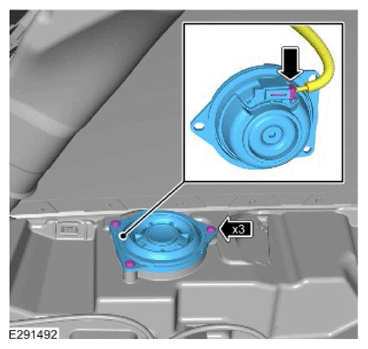
NOTE: Left side is shown, right side is similar.Remove the right loadspace speaker.
- Remove the 3 screws.
- Release the loadspace speaker.
- Disconnect the electrical connector.
Remove the right upper loadspace side bracket.
- Release the 8 wiring harness clips.
- Remove the 2 bolts.
- Remove the 4 nuts.
Vehicles with 5 seats only
- Remove the left loadspace trim panel, (see TOPIx Workshop Manual section 501-05: Interior Trim And Ornamentation - Removal and Installation - Left Loadspace Trim Panel - Vehicles With: 5 Seats/executive Seats).
Vehicles with 7 seats only
- Remove the left loadspace trim panel, (see TOPIx Workshop Manual section 501-05: Interior Trim And Ornamentation - Removal and Installation - Left Loadspace Trim Panel - Vehicles With: 7 Seats).
All vehicles
Remove the left loadspace speaker.
- Remove the 3 screws.
- Release the loadspace speaker.
- Disconnect the electrical connector.
Remove the left upper loadspace side bracket.
- Release the 4 wiring harness clips.
- Remove the 2 bolts.
- Remove the 3 nuts.
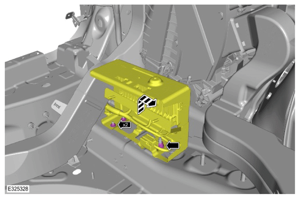
Remove the rear right junction box assembly.
- Disconnect the 4 electrical connectors.
- Remove the 2 bolts.
Reposition the module housing bracket.
- Remove the 2 nuts.
- Remove the nut.
Vehicles with 5 seats only
Remove and discard the right air duct 1.
- Remove the 2 trim clips.
- Release the tab.
Remove and discard the right air duct 2.
- Remove the trim clip.
-
NOTE: Reposition right air duct 4 to allow for the removal of right air duct 3.
Remove and discard the right air duct 3.
- Release the 4 tabs from the 4 studs.
Vehicles with 7 seats only
Remove and discard the right air duct 1 section 1.
- Release the clip.
- Release the wiring harness clip.
-
CAUTION: The right air duct 1 section 2 must not be discarded.
Remove the right air duct 1 section 2.
- Remove the 2 trim clips.
-
CAUTION: The right air duct 2 must not be discarded.
Remove right air duct 2.
- Remove the trim clip.
-
CAUTION: The right air duct 3 must not be discarded.NOTE: Reposition right air duct 4 to allow for the removal of right air duct 3.
Remove the right air duct 3.
- Release the 4 tabs from the 4 studs.
All vehicles
Remove the right D-pillar trim panel mounting bracket.
- Remove the 2 screws.
- Torque: 4.8 Nm
- Remove the 2 screws.
Remove and discard right air duct 4.
- Release the 2 tabs from the 2 studs.
- Remove the trim clip.
Remove and discard right air duct 5.
- Remove the trim clip.
Remove and discard right air duct 6.
- Remove the 2 trim clips.
Remove and discard left air duct 1.
- Remove the 2 trim clips.
-
NOTE: Left air duct 2 must be discarded.
Left air duct 2 has been removed during completion of the 'Headliner Lower For Access' procedure.
Remove and discard left air duct 3.
- Remove the 2 trim clips.






NEW LEFT AND RIGHT AIR DUCT INSTALLATION
- Some variation in the illustrations may occur, but the essential information is always correct.
- Some components shown removed for clarity.
All vehicles
-
NOTE: Repeat this step for the other side.
Remove the cargo net bracket in the order shown in the illustration.
- Remove the 2 bolts.
Vehicles with 5 seats only
Install the air duct.
- Install the trim clip.
Install the air duct.
- Install the trim clip.
- Secure the electrical wiring harness clip.
- Install the tab.
Vehicles with 7 seats only
Install the right air duct 4.
- Install the 2 tabs to the 2 studs.
- Install the trim clip.
-
NOTE: Reposition right air duct 4 to allow for the installation of right air duct 3.
Install the right air duct 3.
- Install the 4 tabs to the 4 studs.
Install the right air duct 2.
- Install the trim clip.
Install the left air duct 1.
- Install the trim clip.
Install the right air duct 1 section 2.
- Install the 2 trim clips.
Install the right air duct 1 section 1.
- Install the clip.
- Install the wiring harness clip.
All vehicles
Install the air temperature sensor into the air duct in the position shown in the illustration.
Install the air duct.
- Secure the retaining tab.
Connect the air temperature sensor electrical connector.
Disconnect the electrical connector from the right roof pod.
Install the air temperature sensor into the air duct in the position shown in the illustration.
Install the air duct.
- Secure the 2 tabs.
Position the left roof pod wiring harness as shown in the illustration and connect the electrical connector.
- Connect the air temperature sensor electrical connector.
Install the duct.
-
NOTE: Make sure the air duct retaining tab is located under the right cargo net bracket, as shown in the illustration.
Install the right cargo net bracket.
- Install the 2 bolts.
- Torque: 6 Nm
- Install the 2 trim clips.
- Install the 2 bolts.
-
NOTE: Make sure the air duct retaining tab is located under the left cargo net bracket, as shown in the illustration.
Install the left cargo net bracket.
- Install the 2 bolts.
- Torque: 6 Nm
- Install the 2 trim clips.
- Install the 2 bolts.
Raise the headliner.
- Secure the 5 clips.
- Secure the 9 magnets.
Connect the 2 headliner harness electrical connectors.
Install the duct in the order shown in the illustration.
- Install the tab.
Install the duct in the order shown in the illustration.
- Install the trim clip.
Install the D-pillar trim panel mounting bracket.
- Install the 2 bolts.
- Torque: 4.8 Nm
- Install the 2 bolts.
Install the module housing bracket.
- Install the 2 nuts.
- Torque: 5.4 Nm
- Install the nut.
- Torque: 48 Nm
- Install the 2 nuts.
Install the rear right junction box assembly.
- Connect the 4 electrical connectors.
- Install the 2 bolts.
- Torque: 6 Nm
Install the left upper loadspace side bracket.
- Install the 4 wiring harness clips.
- Install the 2 bolts.
- Torque: 5 Nm
- Install the 3 nuts.
- Torque: 5 Nm
Install the left loadspace speaker.
- Connect the electrical connector.
- Install the loadspace speaker.
- Install the 3 screws.
- Torque: 1.9 Nm
Vehicles with 5 seats only
- Install the left loadspace trim panel, (see TOPIx Workshop Manual section 501-05:Interior Trim And Ornamentation - Removal and Installation - Left Loadspace Trim Panel - Vehicles With: 5 Seats/executive Seats).
Vehicles with 7 seats only
- Install the left loadspace trim panel, (see TOPIx Workshop Manual section 501-05:Interior Trim And Ornamentation - Removal and Installation - Left Loadspace Trim Panel - Vehicles With: 7 Seats).
All vehicles
Install the right upper loadspace side bracket.
- Install the 8 wiring harness clips.
- Install the 2 bolts.
- Torque: 5 Nm
- Install the 4 nuts.
- Torque: 5 Nm
-
NOTE: Left side is shown, right side is similar.
Install the right loadspace speaker.
- Connect the electrical connector.
- Install the loadspace speaker.
- Install the 3 screws.
- Torque: 1.9 Nm
Vehicles with 5 seats only
- Install the right loadspace trim panel, (see TOPIx Workshop Manual section 501-05:Interior Trim And Ornamentation - Removal and Installation - Right Loadspace Trim Panel - Vehicles With: 5 Seats/executive Seats).
- Install the loadspace floor trim. 34.
Vehicles with 7 seats only
- Install the right loadspace trim panel, (see TOPIx Workshop Manual section 501-05:Interior Trim And Ornamentation - Removal and Installation - Right Loadspace Trim Panel - Vehicles With: 7 Seats).
- Install the smart loadspace 36. compartment floor.
All vehicles
- Install the headliner, (see TOPIx Workshop Manual section 501-05: Interior Trim And Ornamentation - Removal and Installation - Headliner Lower For Access).


