Transfer Fuel Pump -G6-, Checking, Vehicles With 3/4-Cylinder Engine: Notes
Special Tools And Workshop Equipment Required
- Injection Rate Comparison Meter Kit - Remote Cable:VAG1348/3A with Injection Rate Kit - Remote Cable:VAG1348/3-3
- Analog/Digital Multimeter :FLU83III
- Connector Test Set:VAG1594D
- Pressure Tester Kit:VAS6550 with Pressure Tester Kit - Hose 1:VAS6550/1 and Pressure Tester Kit - Hose 2:VAS6550/2
- Pressure Regulator Valve:VAS6550/4
- Measuring container, fuel-resistant
A - Check Fuel Delivery Rate
-- Observe all test conditions. Refer to TEST CONDITIONS .
-- Move the front seats all the way forward.
-- Release and open the fuel filler door.
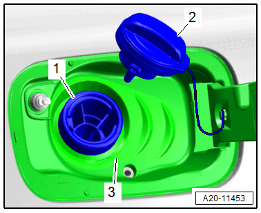
-- Clean the area around the fuel filler neck.
-- Remove the cap -2- for the fuel filler -1-.
Ignore -3-.
With Front Wheel Drive (FWD), Without High Voltage System:

-- Remove the rear bench seat. Refer to BENCH/REAR - SEAT/SINGLE SEAT, REMOVING AND INSTALLING .
-- Unclip the locking flange cover -1- at the tabs in direction of -arrows- using the :3409 .
-- Release the connector safety catch, and disconnect the connector -1- on the sealing flange.

Ignore -2-.
VEHICLES WITH A HIGH-VOLTAGE SYSTEM:
-- Remove The Rear Shelf. Refer to REAR SHELF, REMOVING AND INSTALLING .
-- Remove The Luggage Compartment Floor. Refer to OVERVIEW - LUGGAGE COMPARTMENT FLOOR .
-- Fold the rear seat backrests forward.
-- Remove the subwoofer. Refer to SUBWOOFER -R211-, REMOVING AND INSTALLING .
-- Remove the nuts -arrows 1 to 5- and remove the sealing flange cover -6-.

-- Disconnect the connector -arrow- on the sealing flange by unlocking the connector safety catch.

CONTINUATION FOR ALL VEHICLES WITH FWD:

-- Connect the :VAG1348/3A using the :VAG1348/3-3 and cable from the :VAG1594D to the terminal -1-.
-- 2. Tape the :VAG1348/3-3 with insulating tape -arrow-.
-- Connect the connector terminal -5- to the chassis ground -A- with an adapter cable from the :VAG1594D .
-- Connect the alligator clip to battery "+" -B-.
AWD VEHICLES:
-- Remove the rear bench seat. Refer to BENCH/REAR - SEAT/SINGLE SEAT, REMOVING AND INSTALLING .
-- Unclip the locking flange cover -1- at the tabs in direction of -arrows- using the :3409 .
-- Release the connector safety catch to disconnect the connector -1- on the right sealing flange.

Ignore -2-.
-- Connect the :VAG1348/3A using the :VAG1348/3-3 and cable from the :VAG1594D to the terminal -1-.

-- 2. Tape the :VAG1348/3-3 with insulating tape -arrow-.
-- Connect the connector terminal -2- to the chassis ground -A- with an adapter cable from the :VAG1594D .
-- Connect the alligator clip to battery "+" -B-.
Continuation For All Vehicles:

Risk of injury due to the fuel being under high pressure.
- To reduce the pressure in the fuel system, lay clean cloths around the connection point and carefully loosen the connection point.
-- Disconnect the fuel line -1-. Disconnect the connector couplings. Refer to CONNECTOR COUPLINGS, DISCONNECTING .
-- Connect the :VAS6550 with the :VAS6550/2 to the fuel supply line.

-- Connect the :VAS6550/4 and hold the hose in a fuel-resistant measuring container.
-- Switch on the :VAS6550 -1- by pressing the On/Off button.

To measure the fuel delivery rate, an initial pressure must be created in the fuel line which the fuel pump must work against during measurement. Set the initial pressure using the :VAS6550/4 as follows:
-- Open the shut-off valves -A and B-.
- The levers point in the flow direction.
Risk of fuel leaking.
- The shut-off valve -C- must be closed.
- The lever is perpendicular to the flow direction.
-- Press the remote control switch.
-- Turn the adjusting screw -1- on the :VAS6550/4 to create an initial pressure in the fuel system until the correct initial pressure value is reached.

- Specified Value: 4.0 bar (58 psi) Pressure.
-- Do not turn the adjusting screw -1- any farther.
-- Empty the measuring container.
-- Press the remote control switch for 15 seconds.
-- Compare the quantity of fuel delivered with the minimum delivery rate in the diagram (cm3 /15s).

Voltage at the fuel pump with the engine stopped and the pump running is approximately 2 volts less than the battery voltage.
If the Minimum Delivery Rate is Attained:
- The fuel delivery unit and the fuel supply line are OK.
If Minimum Delivery Quantity is not Obtained, the Following Malfunctions May Be Present:
- Fuel delivery unit faulty.
- Fuel supply line is crushed.
To more accurately locate the malfunction, perform the "pressure test in the fuel supply line" described in the following.
B - Pressure Test in the Fuel Supply Line
- Set up the equipment as if measuring for the fuel delivery rate.
- The :VAG1348/3A is still connected.
-- Turn the :VAS6550 -1- on by pressing the On/Off button.
-- Open the shut-off valves -A and B-.
- The levers point in the flow direction.
Risk of fuel leaking.
- The shut-off valve -C- must be closed.
- The lever is perpendicular to the flow direction.
-- Press the remote control switch.
-- If the fuel flows without bubbles, close the shut-off valve -B- so that the fuel pressure increases.
- The lever is perpendicular to the flow direction.
-- Read the fuel pressure on the :VAS6550 :
- Specified Value: Minimum 6.0 bar (87 psi)
If the Specified Value Is Obtained, Even Though the Fuel Delivery Rate Was Not OK:
- The fuel delivery unit integrated fuel filter is blocked or the fuel supply line is crushed.
If the Specification is Not Attained:
- Fuel delivery unit faulty.
C - Checking Residual Pressure
-- Watch the pressure decrease on the :VAS6550 while checking the residual pressure and checking for leaks:
- After 10 minutes there must be a residual pressure of at least 3 bar (43 psi).
If the Residual Pressure Drops Below 3 bar (43 psi):
- Check the fuel lines and their connections for leaks.
- The check valve in the fuel pump leaks: replace the fuel delivery unit. Refer to FUEL DELIVERY UNIT/FUEL LEVEL SENSOR, REMOVING AND INSTALLING .