Control Diagram
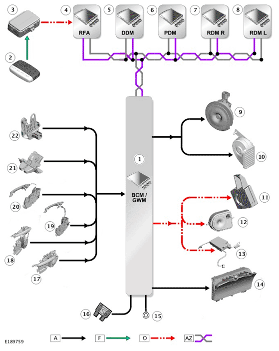
A = HARDWIRED: F = RADIO FREQUENCY (RF) TRANSMISSION: O = LOCAL INTERCONNECT NETWORK (LIN): AZ = HIGH SPEED (HS) CONTROLLER AREA NETWORK (CAN) BODY BUS.
| ITEM | DESCRIPTION |
|---|---|
| 1 | Body Control Module/Gateway Module (BCM/GWM) |
| 2 | Smart Key |
| 3 | Radio Frequency (RF) receiver |
| 4 | Remote Function Actuator (RFA) |
| 5 | Driver Door Module (DDM) |
| 6 | Passenger Door Module (PDM) |
| 7 | Rear Door Module (RDM) - Right |
| 8 | Rear Door Module (RDM) - Left |
| 9 | Passive sounder (where fitted) |
| 10 | Horn |
| 11 | Immobilizer Antenna Unit (IAU) |
| 12 | Battery Back-Up Sounder (BBUS) (market dependent) |
| 13 | Interior motion sensor (in overhead console) |
| 14 | Instrument Cluster (IC) |
| 15 | Ground |
| 16 | Supply |
| 17 | Front door latch mechanism with ajar switch - Driver |
| 18 | Front door latch mechanism with ajar switch - Passenger |
| 19 | Rear door latch mechanism with ajar switch - Right |
| 20 | Rear door latch mechanism with ajar switch - Left |
| 21 | Tailgate latch |
| 22 | Hood switch |